Building a Yankee Nipper
by:Rick “catdaddy” Blankenship
Greetings from the hills of Oklahoma. Last issue I mentioned that I would review the rules in various areas of the country for the unofficial event of Speed Limit Combat (S.L.C.), but after talking with Tim Ehlen, he convinced me to do a build article for the Winter issue and wait until the Spring issue to review the various rules that are used in each district. If you remember, in the last issue I talked of my mentor, Jim Carpenter, and his S.L.C. design, the “Yankee Nipper”. Jim named his design because of the nipping of the streamer (for multiple cuts) that is the preferred tactic of S.L.C. compared to the go for the kill cut in AMA fast. He also adopted the New England Lobster as a mascot for his very easy to build highly competitive S.L.C. plane. The name works very well because it was designed with that famous “Yankee” ingenuity and it gives you every opportunity to “nip” away at those streamers.
Why the Yankee Nipper? Basically there are three main reasons one should choose the Nipper when considering to build a S.L.C. plane. First: EASE OF CONSTRUCTION. You should be able to build a Nipper in about 2 to 3 total hours not counting overnight glue curing time. If you pre-make all the components, it’s nothing to build a 4-ship fleet in a weekend. Everything about the Nipper is simple. Jim kept it this way to allow rapid construction and repair. I believe he succeeded in this part of his design. Second: DURABILITY. Another of Jim’s design criteria was to have a durable ship that would survive not only a ground pounding, but maybe a mid-air or two as well. The solution here has two main parts, the pine center rib and the drywall reinforcing tape. These two items, when properly constructed and applied, give the Nipper amazing durability. Third: COMPETITIVE. The last requirement Jim had was for a design that would be competitive. Like all combat pilots, competition is a strong driving force, so Jim’s design had to turn well and hold in the wind. It does this as well as any I’ve seen. I love the fact that with the Nipper I can maneuver upwind when the winds are a little stiff and keep all but the most aggressive pilots from doing the same. Of course almost all combat pilots are aggressive, but if their planes can’t deal with the wind, that aggressiveness can be fatal.
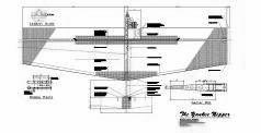
I will try and outline the steps for constructing one of the versions of the Yankee Nipper. I highly suggest that you contact Jim Carpenter at oldrustylines@aol.com and ask for a set of plans. He has a set that will work for the tapered leading edge version. Yes, there are several versions, mostly different wing areas, but there are two different wing shape versions as well. There is a straight leading edge and a tapered leading edge, each of which has a different boom length or tail moment. If you’d like the straight leading edge 500, Download the free PDF plan above.
Straight leading edge version uses a 4” boom moment from wing trailing edge to elevator leading edge. If you go with the tapered leading edge version, you must increase the moment to 6”. Phil Cartier of “The Corehouse” can supply you with the wing cores as well as the .411 carbon fiber booms, and can be contacted at philcartier@earthlink.net. There are several different wing areas ranging from 460 to 500, just tell Phil what you’d like and he will set you up with 4 sets for a very reasonable price.
If you’re wondering about the two different leading edge versions, the most current version is the straight leading edge. Jim developed this version in order to get a little tighter turning radius. It is the version that Jim currently campaigns. The tapered leading edge version is still competitive, but does not turn as tight as the newer version.
Whatever version you choose, your target weight should be between 22 and 25 oz., depending on engine and tank setup. While bladders are very popular and are used quite extensively, I dislike them and see no need to use them if a chicken hopper works, and for me, they do. Hard tanks have their own set of problems, but I’m willing to deal with those for the ease of use come match time. I run several different engines, the LA 40, Fox Mk6, and the OS 32 SX. The 32 SX is by far the best engine to run. It starts with 1 flip and will hot start better than anything I’ve seen. I use 9-4 props on all three motors and 10-22 fuel. I also use .21 lines instead of the .18 that are the minimum requirement. At 75 mph speeds, .21 size lines do not have a big impact on performance. What they do give you is incredible durability in a line tangle, especially if your opponent is using .18 lines.
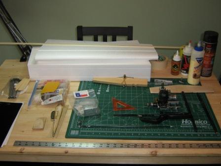
After you receive your plans and wing cores, you will need the following:
• ¾” white pine (center rib) 10 ½”x 2”x ¾”
•Corehouse .411 carbon fiber tube
•Corehouse lightweight covering
•.155 carbon fiber pushrod
•Aluminum engine mounts
•3/32” piano wire
•Drywall joint reinforcing tape
•Alphatic glue (white glue)
•3.25 GRW Chicken hopper tank
•(2)-1/8”x 3/8”x 48” spruce wing spars (per plane)
•Sheet of ¼” balsa (hard) for elevator
•Sheet of 1/8” balsa - wing tips and tank cut out
•(2) acid brushes
•(2) disposable foam brushes
•Epoxy glue 5 min and 30 min
•Paper towels
•(2) ½ oz. fishing weights
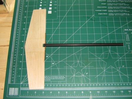
The Nipper design is centered around the ¾” pine center rib and carbon fiber boom. This is the backbone of a very durable SL combat plane. The foam wings are attached to the center rib with spruce hardwood spars and reinforced with common 2 ½” drywall tape applied with a water-base glue.
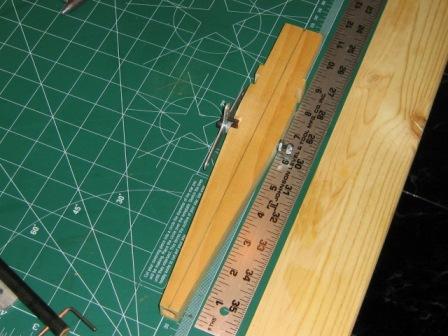
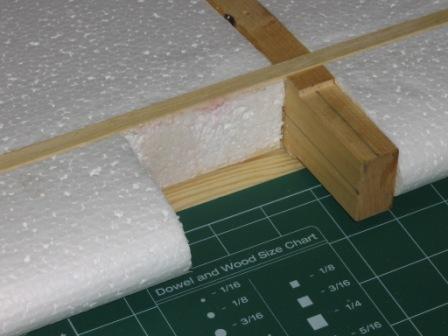
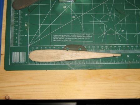
Wing assembly (fig. 1-3):
First step is to apply 5 minute epoxy to the sides of the center rib. You may also use 3M 77 spray adhesive if you have the kind that does not attack foam. The formula has changed and is not as friendly to foam as in the past. Be careful here because the foam cores can quickly become ruined if you’re not careful. If you use the spray, make sure you roll the rib onto the core so that it aligns properly. Again, you only have one shot when using the spray, so be careful. While the epoxy is heavier, it is much easier to work with and get the wings properly attached and aligned on the center rib. Once you have both wings attached to the center rib, you may now place the 1/8”x 3/8”x48” spruce spars into the wing spar slots and thru the center rib. Use your white glue to attach spars. I run a bead of glue in the wing spar slots and smooth out with an acid brush. Use a generous amount of glue here and wipe any excess off with a paper towel. Use plain masking tape to hold spar in place and let dry over night.
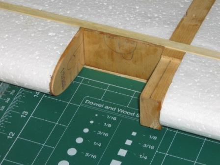
Note: Figure #3
The hole drilled in the end of center rib for boom MUST be straight and parallel with center rib drill to a depth of 3”.
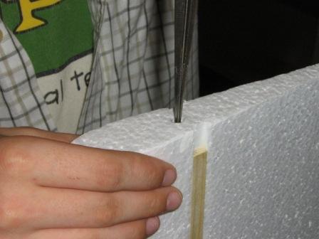
Wing assembly continued (fig. 4-6):
After spars dry overnight, remove the masking tape that held them in place. Measure and cut fuel tank compartment. Cut 1/8” hard balsa to cover tank cutout. Use vertical grain at spar and horizontal grain from spar to leading edge.
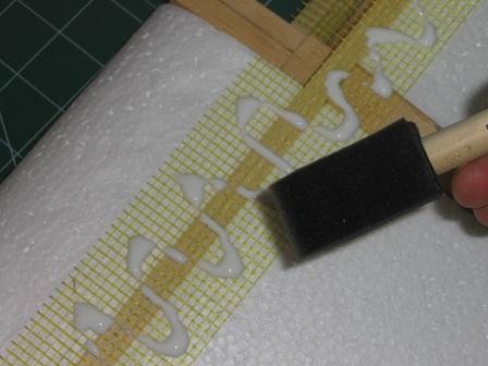
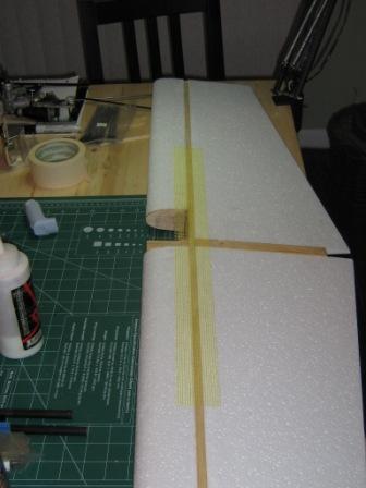
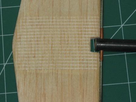
Wing assembly continued (fig. 7-9):
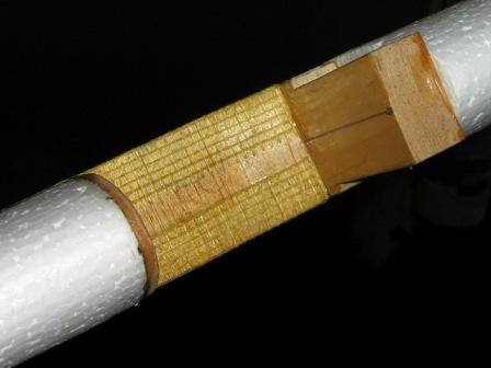
Apply drywall reinforcing tape. Use 24” piece, center over spar and center rib. Use foam brush and liberal amounts of white glue to attach reinforcing tape to wing. Wipe excess glue with paper towels. Do both top and bottom of wing. Cut and fold over at tank cutout. Use epoxy to glue down drywall tape in tank compartment. This also fuel-proofs the tank compartment 1/8” balsa.
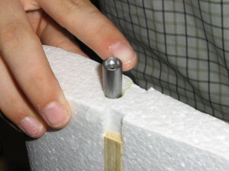
Wing assembly continued (fig. 10-12):
Wing tips can be installed at this time, however, make sure you install at least 1 oz. lead wing tip weight on the outboard wing. I use (2)-1/2 oz. fishing wt. for a total of 1 oz. and a little poly-u glue. Make the wingtips from 1/8” hard balsa. I reuse old wingtips from planes that don’t survive a match. Cannibalize everything you can and reuse. Another option for the outboard wing tip would be to trim ¾” from the tip to compensate for the ¾” center rib thickness. The standard 48” spruce wing spar will be ¾” short at the outboard wingtip. I normally just fill in the wing spar slot with light weight spackling compound and sand smooth. Jim Carpenter recommends that you trim the outboard wing tip down by ¾”.
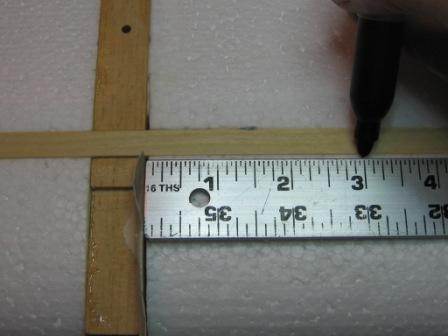
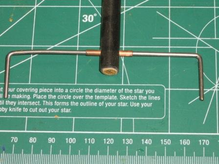
Elevator and boom assembly (fig. 13-15):
Before we can finish the wing, we must finish the boom and elevator assembly. We start with a .411 diameter carbon fiber tube from Corehouse. Cut to 9” length, if you’re building a tapered leading edge wing, then the boom length will be cut to 11”. Fill the end of the boom with a 1” piece of hard wood dowel and epoxy. This will keep the elevator hinge assembly from tearing out of the end of the carbon boom during a crash. Once the dowel has dried, set up a jig to drill a 1/8” dia. hole ¼” from the end of the boom. Install a 1/8”x 1” brass or copper tube into the tail boom hole and secure with epoxy. Using the 3/32” piano wire, cut a piece 6” in length and bend 1” @ 90, feed through the brass or copper tube and make another 1” @ 90 bend. Tweak bends so that they are parallel. Using ¼”x 12” hard balsa for elevator, cut a ¼” notch to fit around the end of the boom and drill (2)-3/32” holes 4” apart for piano wire hinge. The shape of the tail is not critical, but it should be at least 12” long. I start with 2 3/4” at the center and taper to 2” at the ends. Before you epoxy the piano wire hinge into the elevator, use the reinforcing drywall tape and white glue at the center of the elevator for added durability. You may also want to cut a groove in the leading edge of the elevator at the wire hinge and apply epoxy when installing elevator to hinge.
Wing assembly continued:
Once the boom and elevator assembly is complete, it’s time to epoxy the boom inside the center rib. Make sure everything is aligned before the epoxy sets. It’s critical that the elevator is parallel to the wing or your combat plane will not fly correctly. Once the boom/elevator assembly is set and epoxy has cured, you now must cut triangular pieces from ¼” balsa to fill in between the wing trailing edge and the boom. Glue these into place with white glue. The final step for the wing will be to cut (2)-14” pieces of drywall reinforcing tape and glue to trailing edge centered at boom. Use the same method used to reinforce the main wing spar on both sides of trailing edge. Once the white glue has dried, use an X-acto blade to trim the drywall tape flush with the trailing edge. Something I like to do is to take 1” reinforced package tape or heavy clear plastic tape and reinforce the entire trailing edge of the wing with 1/2” on each side.
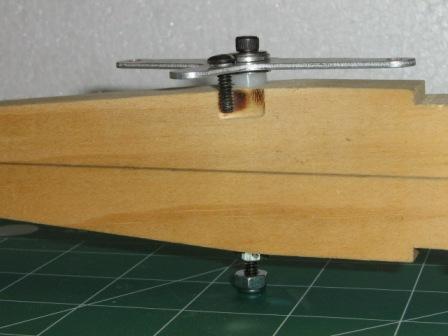
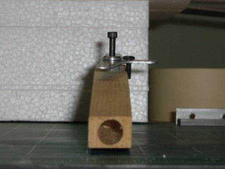
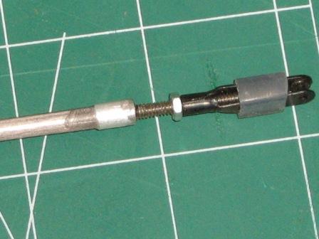
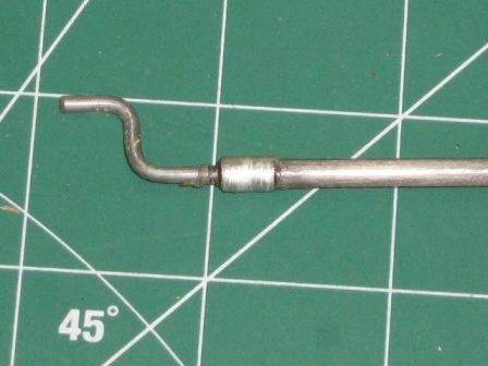
Miscellaneous items (fig. 16-18):
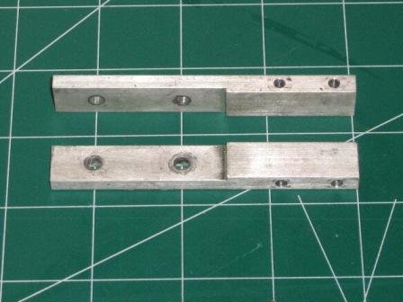
The pushrod is something I make from .155 carbon fiber tube. Mount the belcrank after taping the inside hole and installing a 6-32x1/4” screw to act as a stop to limit the motion of the belcrank. You should be able to see the notch in the center rib in figure #2. Once the belcrank is installed, take a measurement from belcrank to leading edge of elevator. Subtract approximately 1” from the measurement and cut the .155 carbon fiber pushrod. Using aluminum tubing that fits the outside diameter, I cut 1/2” piece and JB weld it to each end of the pushrod. After the JB weld sets, use a 4-40 tap and thread the inside of the carbon fiber tube, going in no more than 1/2”. Then, using threaded rod, make your end pieces per figures 16 and 17 and screw into ends and JB weld into place. The plans call for aluminum motor mounts that have a step that allows various size motors to be used simply by flipping the orientation of the mount which will change the clearances for the motor crankcase. These can easily be made by someone with a mill or you can purchase them from several sources on the Internet.
Miscellaneous items continued:
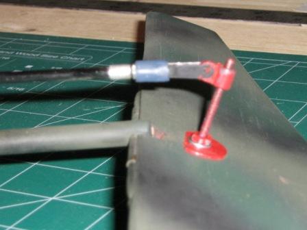
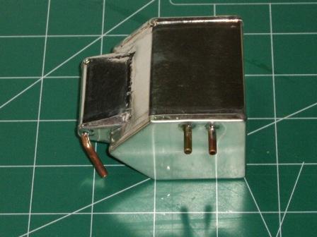
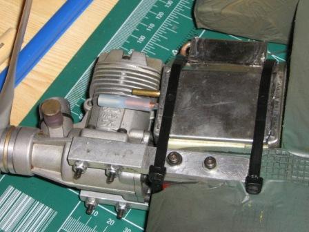
I use the J&J trick elevator horn purchased from Jim Carpenter. It’s simply a couple of fender washers with a 1” 4-40 bolt and a plastic RC gizmo that allows you lots of adjustment. See figure 19. As mentioned earlier, I don’t like bladders. At 75 mph, the GRW Chicken hopper tank works fine. Nobody will be waiting on you at the circle when it comes time to fly. When I walk out to the circle, I’m ready to go because I don’t have to mess with a bladder. Others won’t fly without a bladder so you’ll have to decide which type of fuel tank is right for you. If you use a GRW 3.25 tank secure it to the center rib with double sided foam tape. The feed line should be no more than ¼” above the centerline of the engine. Once you have the tank located and secure to the center rib with the foam tape use (2)-14” zip ties to firmly secure tank to center rib. (Figure 21)
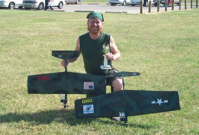
Finish and Final thoughts:
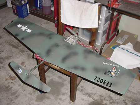
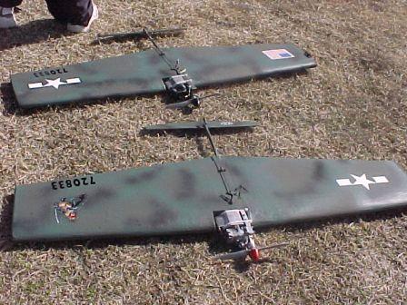
I’ve used several types of covering and finishes on my planes; Fastcal, Monokote, Corehouse Covering and Plastic Laminate have all been used with success. I also usually give up an ounce or two and camo paint my birds with Rustoleum camo colors and a couple of stickers. Most guys don’t waste the time, money, and effort on anything too fancy because of the possible short life of the plane. My thoughts are if they don’t look cool I don’t want to fly them.
I hope you guys can make sense out of my attempt at a building article and that you build a fleet of Nippers for the new season. I assure you if you build them light and straight and power them with a reliable engine, you will not be disappointed. Don’t hesitate to contact Jim Carpenter; he loves nothing more than to talk about his Nipper design, and he’d be more than happy to answer your questions.